3-DOF Robot Arm Design and Fabrication
Robotics ·Overview
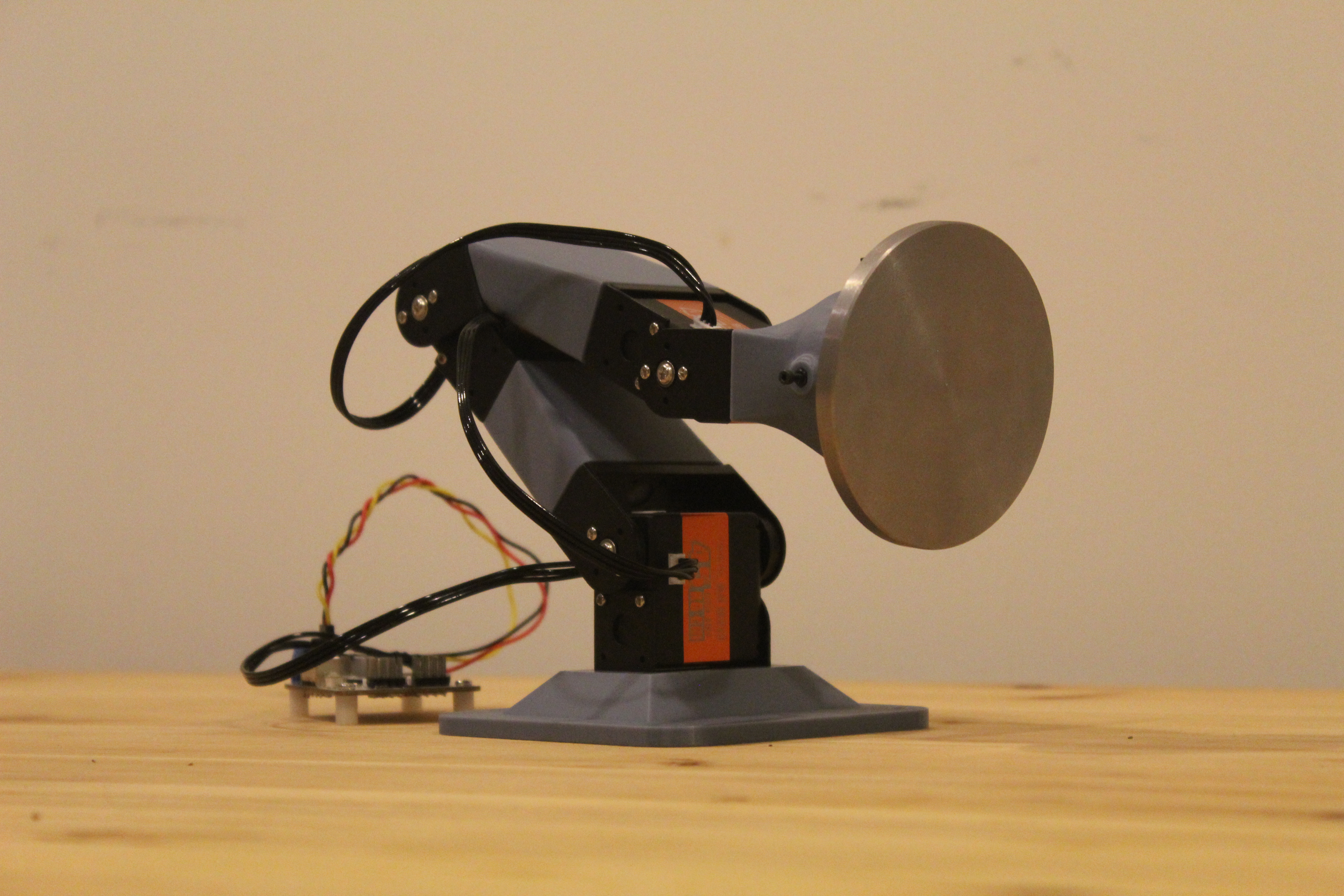
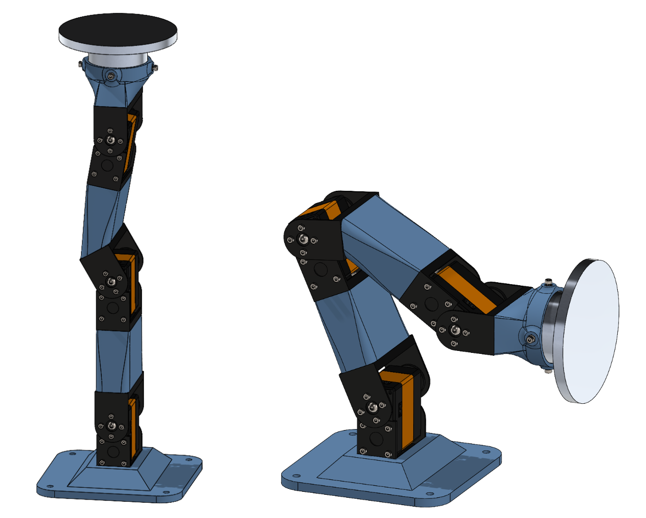
For RBE 501 (Robot Dynamics) at WPI, our team designed a 3-DOF planar robot arm capable of moving a 500g payload between three defined positions. The course project required kinematic analysis, CAD modeling, trajectory generation, dynamics analysis, and motor selection—but we chose to go further and physically fabricate the arm as well.
Kinematic Design
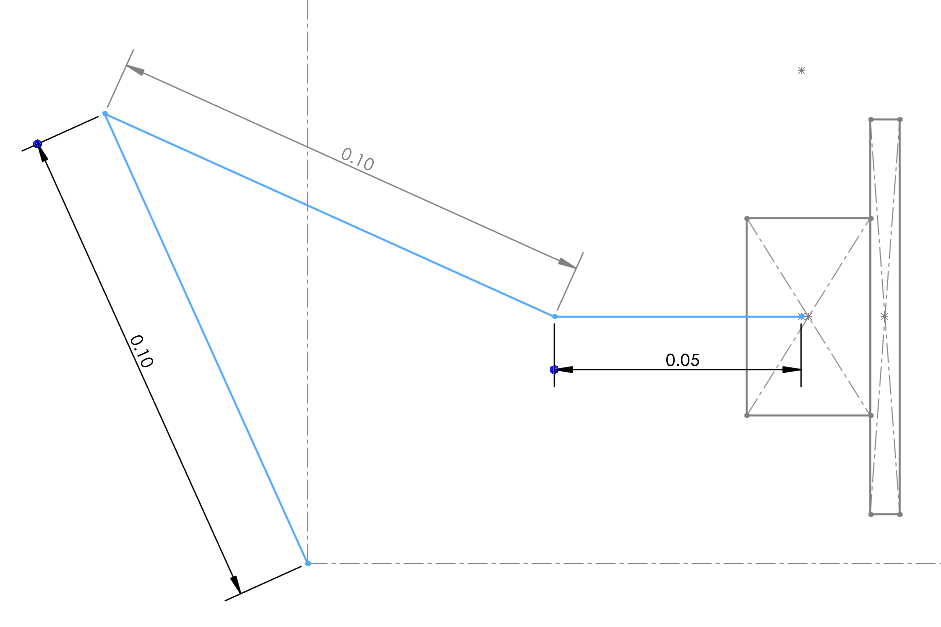
We designed a planar arm with link lengths of 10cm, 10cm, and 5cm. Forward kinematics were computed using the Product of Exponentials (PoE) formulation, while inverse kinematics used a geometric approach with the Law of Cosines and Law of Sines to find closed-form solutions for each target pose.
Trajectory Generation
Smooth trajectories were generated using quintic polynomials in joint space. The polynomial coefficients were computed to satisfy constraints on position, velocity, and acceleration at the start and end of each motion segment—ensuring zero velocity and acceleration at rest positions.
Dynamics and Motor Selection
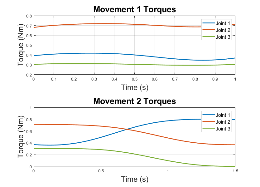
We analyzed joint torques using the Recursive Newton-Euler (RNE) algorithm, computing both gravity compensation and inertial torques at each timestep. Based on the maximum torque, velocity, and acceleration requirements, we selected Hiwonder HTD-45H servo motors, which provided a safety factor of approximately 5.5x on torque.
What I Learned
This project gave me hands-on experience connecting theoretical robotics concepts to physical hardware. Deriving kinematics and dynamics by hand, then validating them against a real system, reinforced how small modeling assumptions affect real-world behavior. It also highlighted the value of doing rough calculations early—we estimated motor requirements before completing the full analysis, which let us start fabrication in parallel.