
motion planning ·
Transmission: Pulling a Mainshaft with BiRRT
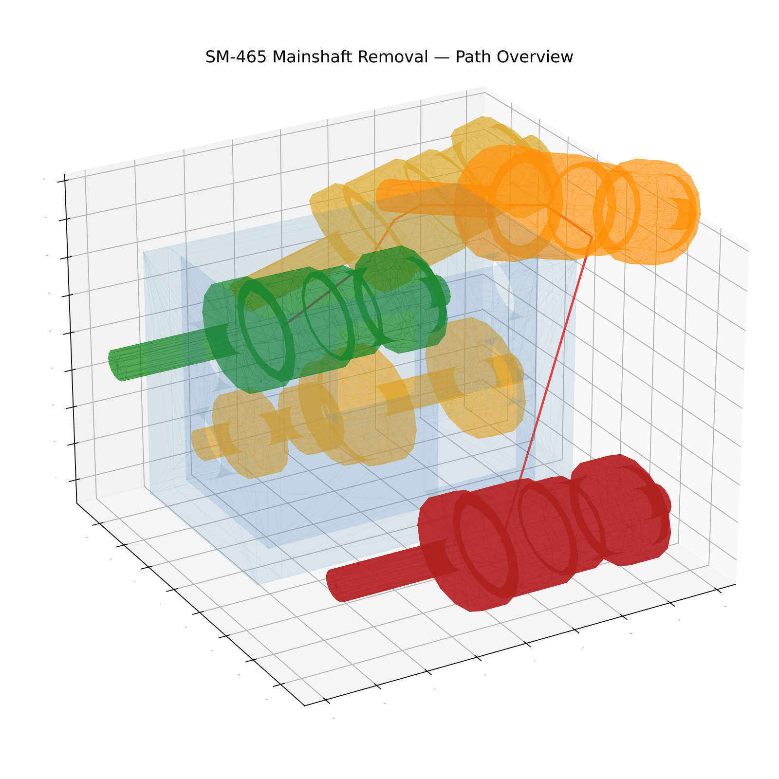
Disassembly planning: find a collision-free path that extracts the mainshaft from an assembled SM-465 four-speed manual transmission, past the countershaft and out of the enclosure. The planner is Bidirectional RRT growing one tree from the assembled pose and one from the removed pose; collision checking runs on triangular meshes through FCL. Built for RBE 550 (Motion Planning) at WPI.
Full report (PDF) ↓ Explore the codebase ↓
A State Space With a Correctness Guarantee
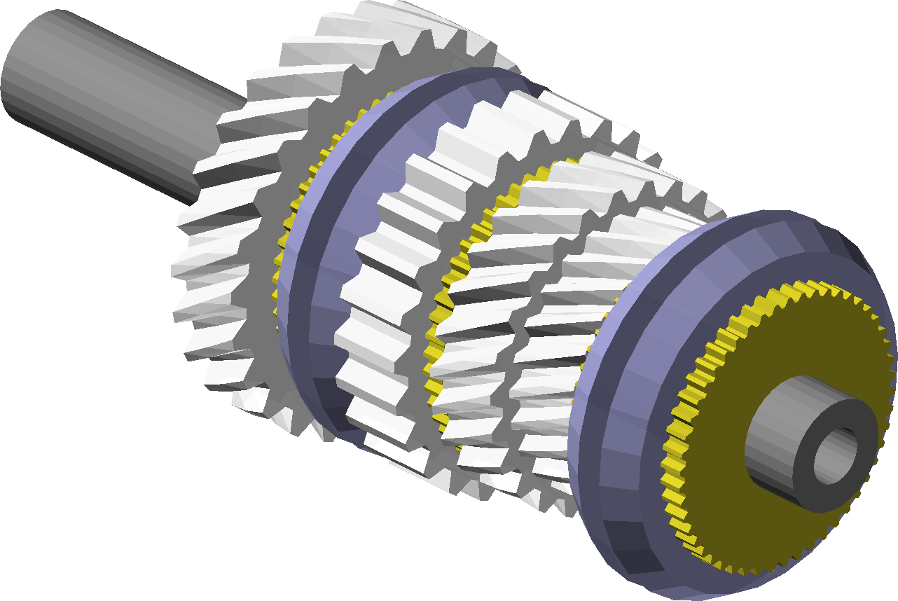
The real mainshaft is a thicket of helical gears and synchronizers. The planner never sees any of that: every component is replaced by a straight cylinder at the part’s outermost radius, so the simplified shaft fully encapsulates the detailed one — any path that’s collision-free for the cylinders is guaranteed collision-free for the real geometry. The simplification is a formal argument, not an empirical tuning knob.
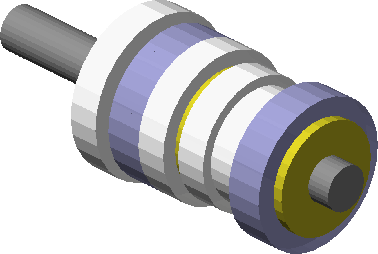
Encapsulation buys two things. Collision checks get cheaper — no tooth geometry in the meshes. And the cylinder model is rotationally symmetric about its own axis, which makes one rigid-body degree of freedom redundant: the usual 6-DOF pose space collapses to five variables,
where are spherical angles orienting the shaft axis.
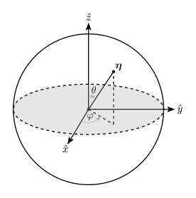
Spherical angles avoid gimbal lock (the singularities at are orientations the shaft never visits) and are simpler than quaternions. Distance in this space is Euclidean position distance plus the great-circle angle between shaft axes, weighted by half the shaft length — so a rotation contributes the arc its tip sweeps, not an arbitrary constant. Segment interpolation uses SLERP on the axis so intermediate poses swing smoothly.
One tempting further cut — dropping entirely, since the extraction motion only needs to pitch the shaft upward — was considered and rejected: for this enclosure it happens to hold, but the planner has no general guarantee of it, and BiRRT converged in seconds without the help.
Collision Checking
Both shafts and the enclosure are built as trimesh boolean unions mirroring the provided OpenSCAD model, then uploaded once to FCL as BVH models. A pose query rotates and translates the mainshaft object, then tests it against the two static bodies. Path segments are checked by sampling interpolated poses about every 5 mm of travel.
One wrinkle: with gears as full-radius cylinders, the meshing gear pairs of the assembled transmission are in collision by construction. The start pose is raised slightly in Z to clear them — equivalent to the real shaft getting an initial straight lift before following the planned path.
BiRRT
The planner follows Kuffner and LaValle’s RRT-Connect: two trees, one rooted at each end of the problem, alternating turns. Each iteration extends the active tree one bounded step toward a random sample, then the other tree greedily grows toward the new node until it either connects or hits an obstacle.
function BIRRT(start, goal):
    T_start.init(start),  T_goal.init(goal)
    for k = 1 to K:
        active, target ← alternate(T_start, T_goal)
        new_node ← EXTEND(active, RANDOM_SAMPLE())
        if new_node exists:
            conn ← CONNECT(target, new_node.pose)
            if conn exists:
                return ASSEMBLE_PATH(active, target, new_node, conn)
    return failure
The raw path then goes through 200 rounds of probabilistic shortcutting — pick two random waypoints, replace everything between them with a direct edge if it’s collision-free.
Results
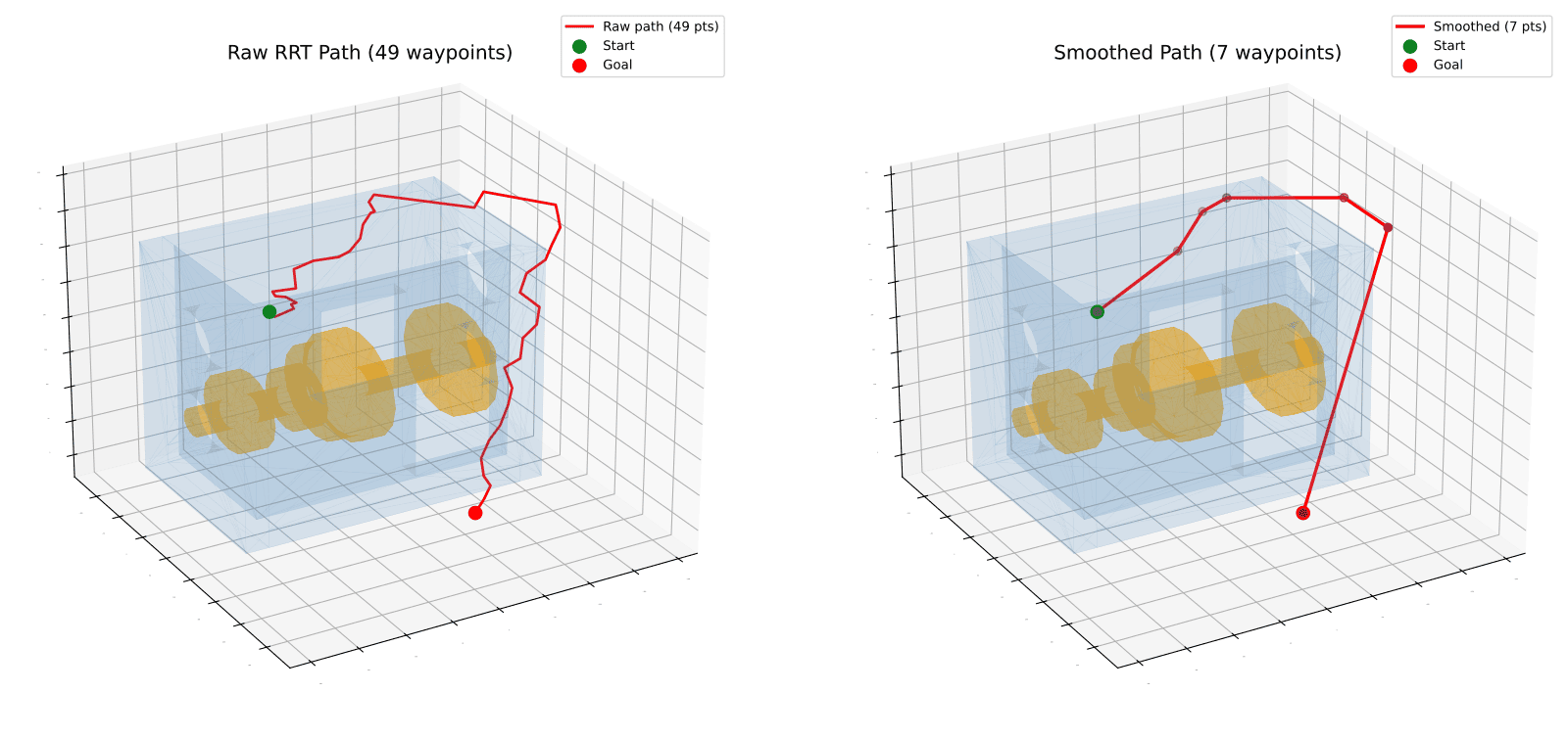
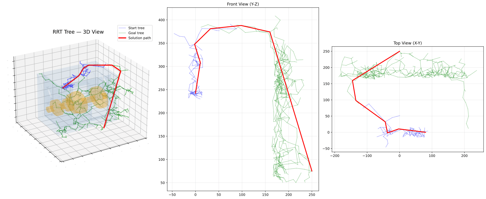
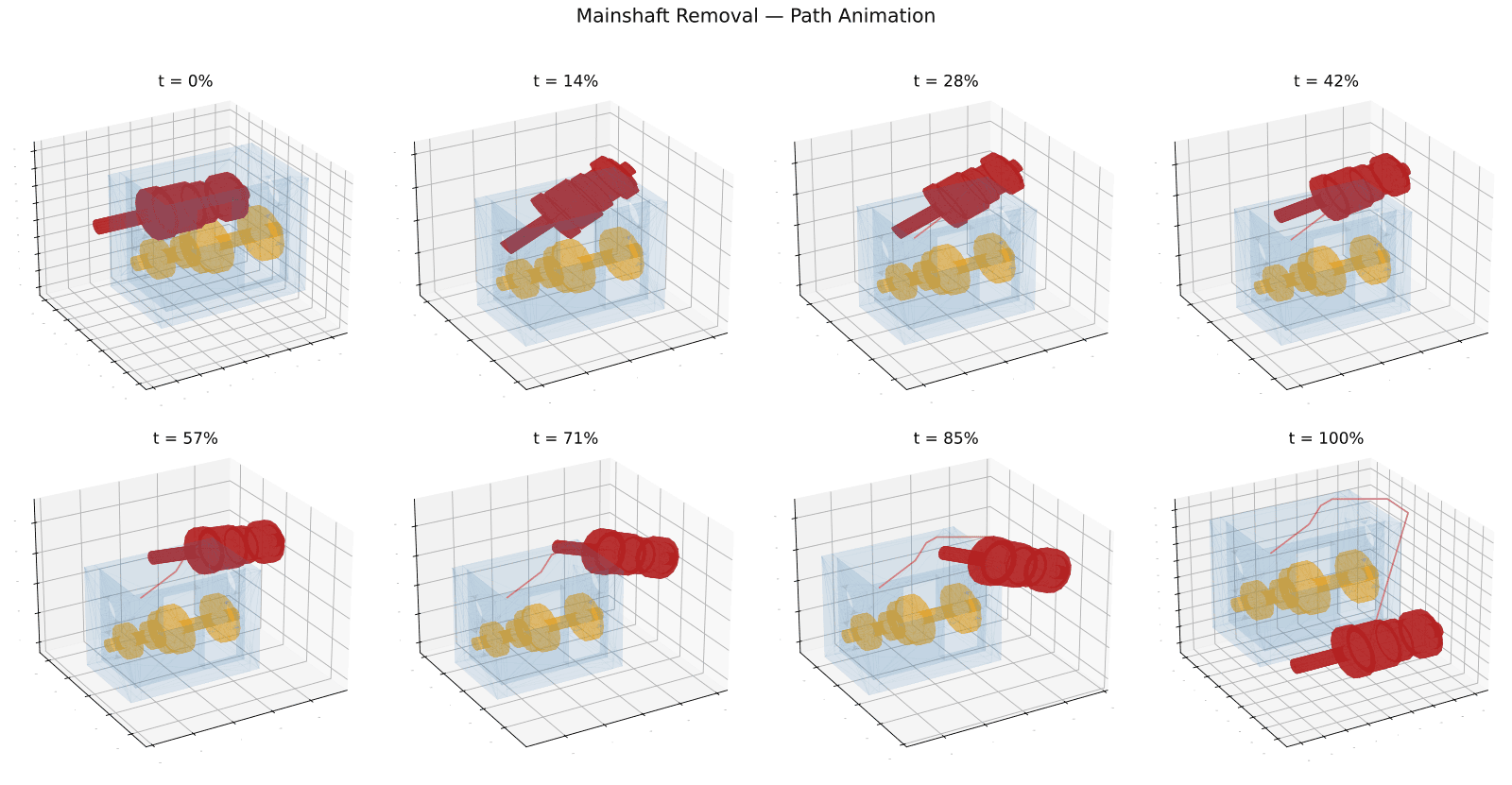
The planner reliably converges within a few thousand iterations. The tree structure tells the geometric story: the start tree stays small — boxed in by the enclosure, most extension attempts fail — while the goal tree grows freely in the open until it envelops the enclosure and the two meet over the top.
References
- Kuffner, J. J. & LaValle, S. M. RRT-Connect: An Efficient Approach to Single-Query Path Planning, ICRA, 2000.
- Geraerts, R. & Overmars, M. H. Creating High-Quality Paths for Motion Planning, IJRR, 2007.
- trimesh and python-fcl (bindings to the Flexible Collision Library).